|
DESCRIPTION - Single reflex band pass enclosure project.
OBJECTIVE - Using optimum alignment calculated and agreed upon by both driver manufacture and this team - Determine and document the gap between optimal max. output and driver failure. OBJECTIVE - Using observations and prior documentation, increase the gap. OBJECTIVE - Raise optimal max. output.
DRIVER MANUFACTURE - Stillwater Designs
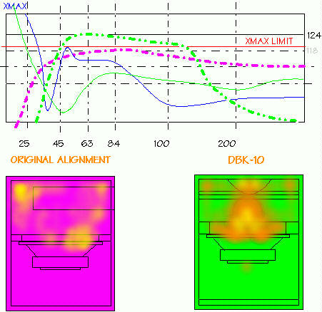
OBSERVATION - First of all it was difficult to repeat the test three times for verification because the thiel smalls measured differently on the three samples. We have determined that to accurately average the figure for optimal max. output and the failure point, several additional woofers will have to be destroyed. For this reason, we have selected to keep the current figure above, and allow for a 20 % variance. OBSERVATION - In determining the gap, 2.5 dB/140watts we must remember this gap is applicable only to the frequency band of the measured output. The gap changed on further tests as optimal alignment was changed so as to reduce the bandwidth and increase output. OBSERVATION - To raise the optimal max. output we found that the gap must be narrowed rather than increased. Increasing the failure point is also increasing the starting point of the gap or optimal max. output. When the thermal limit is reached we have a new failure type which voids the project. OBSERVATION - failure point is the result of non linear travel of the voice coil in the magnetic gap. We have found that the circuit impedance changes during this condition causing reduced dampening by the amplifier as well as uneven air movement across the coil creating hot spots. The port position in the vented chamber was moved 13 times to reduce the condition. All that happened is that the location of the hot spots moved in accordance with the port location suggesting a direct relationship between the two. OBSERVATION - By eliminating the port tube and using the equivalent duct area to achieve the same FB we saw a noticeable increase in the optimal max. output and failure point. This we conclude is due to the more evenly distributed air pressures on the cone surface reducing the twisting and rocking condition prior to the failure point. OBSERVATION - Several duct designs have been tested. The improvements are coming harder and harder now, however we have succeeded in reversing the failure type. We now have thermal failure with little evidence of mechanical damage. Our new adjusted gap is 3.3 dB/84 watts. The optimal max. output has been increased to 118.5 dB at 209 watts RMS. OBSERVATION - Additional work has been done with the duct design. By adjusting the bandwidth to 38hz to 250hz with a 9db hump at 74 cycles the duct length was such that it could be exactly terminated at the center point of the driver. By introducing an angle tangent to the speaker cone on the leading edge of the duct, we were able to reduce mach speed on the duct and improve linear travel of the voice coil. OBSERVATION - By creating a reduction at the exit point of the duct in the shape of a half circle we were able to incorporate the principles of varovents and horn loaded enclosures by creating a rubber throat effect on the FB, now allowing it to change based on frequency. The result of this was now a wider bandwidth with only a 4dB hump. Rather than the peek amplitude of the hump decreasing, the rest of the bandwidth shelved up. OBSERVATION - We have observed after trying drivers of various specs not matching the design original that this duct design is offering similar performance in different band locations, meaning while the response is changing with different drivers the percentage of increase is not. All alternate drivers experienced thermal failure rather than mechanical. All alternate drivers showed an increase in max. optimal output and a raised failure point. Several of the lower power drivers demonstrated over double their rated power handling. OBSERVATION - It would seem as an unexpected result of this project that we have more blown woofers laying around than we know what to do with, and an enclosure that gives acceptable results with almost any woofer designed for sealed enclosures. The reference box from Rockford containing two RFP12's exhibited no better performance than half of the alternate 10" single alignments tested. The original C-10 driver outperformed the reference RFP box by 2.5db at any given output level in the frequency band between 40 and 80 cycles.
Decware is a trademark of High Fidelity Engineering
Co.
|
