DECWARE
Zen Triode Amplifier
Model SE84B
KIT ASSEMBLY INSTRUCTIONS
TESTING
| MODEL SE84B |
|
|
Position 1 of this switch causes the bias resistor to read around 4.6 Volts when read on pin 3 or pin 8 of the 6N1P. Position 2 of this switch causes the bias resistor to read around 2.6 Volts when read on pin 3 or pin 8 of the 6N1P
|
|
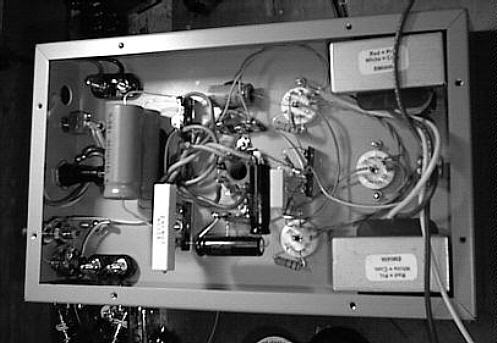
LAYOUT SE84B
|
| MODEL SE84C |
 |
Position 1 of this switch causes the bias resistor to read around 4.6 Volts when read on pin 3 or pin 8 of the 6N1P. Position 2 of this switch causes the bias resistor to read around 2.6 Volts when read on pin 3 or pin 8 of the 6N1P
NOTE: The working voltages of SE84B and SE84C are virtually the same. |
|
PARTIAL LAYOUT SE84C
|
| MODEL SE84CS |
 |
Position 1 of this switch causes the bias resistor to read around 4.3 Volts when read on pin 3 or pin 8 of the 6N1P. Position 2 of this switch causes the bias resistor to read around 2.3 Volts when read on pin 3 or pin 8 of the 6N1P
|
|
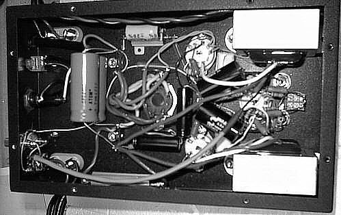
LAYOUT SE84CS
|
|
NOTES: To test your amplifier before trying to play it, the first thing is to see where the voltages land. Above are schematics of the various filter sections of the power supply. The yellow wire with the stripe coming from the power transformer is the rectified B+ that connects to the first section of the filter network. This is point A. Take your meter and connect the ground to the ground wire in the chassis and read the voltages at the illustrated points. To test these voltages, you should have the volume pot turned all the way off, and no load hooked to the amplifier. Also the position on the input stage bias switch will change the voltages so we will list both values for each point.
|
(C)
1998 by High Fielity Engineering Co.
www.decware.com